


High Performance Butterfly Valves
TABLE OF CONTENTS
1.0 Definition of Terms
2.0 Introduction
3.0 Valve Indentification
4.0 Installation
5.0 Maintenance
6.0 Seat replacement
7.0 Field adjustments
8.0 Figures
READ AND FOLLOW THESE INSTRUCTIONS
SAVE THESE INSTRUCTIONS
1.0 DEFINITION OF TERMS
WARNING | indicates a potentially hazardous situation which, if not avoided,could result in death or serious injury. |
CAUTION | indicates a potentially hazardous situation which, if not avoided,may result in minor or moderate injury. |
NOTICE | Used without the safety alert symbol indicates a potential situation which, if not avoided, may result in an undesirable result or state, including property damage. |
2.0 INTRODUCTION
2.1 The SERIES 5000 high performance butterfly valve combines the advantages of trunnion-type ball valves with the easy operation, light weight, and low cost of butterfly valves. One basic design is suitable for a wide range of services, including oxygen, chlorine, sourgas, vacuum, and steam applications.
2.2 FEATURES INCLUDE:
2.2.1 Bubble tight shutoff provided throughout a wide range of operating conditions.
2.2.2 Suitable for both modulating and on/off services, the SERIES 5000 butterfly valve is easily automated with your choice of manual operators, electric and pneumatic actuators, positioners, and controls.
2.2.3 External travel stop for preventing overtravel of disc in opening and closing.
2.2.4 Uninterrupted gasket sealing faces.
2.2.5 Extended neck body for providing pipe insulation clearance of 60mm.
2.2.6 Blind bottom body design up to DN 300.
2.2.7 Bearing seal for protecting bearings from particle ingress.
2.3 Additional information about TIPBV SERIES 5000 butterfly valves-including application data, engineering specifications, and actuator selection is available from your TIPBV distributor or sales representative.
3.0 VALVE IDENTIFICATION
All TIPBV SERIES 5000 valves are provided with an identification tag with the following data printed on it:
● | SIZE | CLASS | ■ | |
BODY | DISC | |||
STEM | SEAT | |||
DESIGN | API 609/EN558-1 | |||
FIG. | ||||
RATING: | ||||
■ I PREFERRED FLOW DIRECTION . | ||||
>SIZE: Valve size e.g. DN 150
>CLASS: Pressure rating of mating flange
>BODY: Material grade of body/seat retainer e.g. WCB, CF8M etc.
>DISC: Material grade of disc e.g. CF8M
>STEM: Material grade of stem e.g. 17-4PH
>SEAT: Material of seat e.g. R-PTFE
>DESIGN: Valve reference design standard
>FIG: Valve or instrument tag number provided by customer
>RATING: Applicable temperature range of valve
4.0 INSTALLATION
4.1The SERIES 5000 valve is designed to be mounted between EN, DIN and JIS flanges. When the valve is open, the disc will extend into the pipe on both sides of the valve 一 further on the body side than the seat retainer side of the valve. Piping must be large enough to allow the disc to clear the pipe. Table 1 shows the minimum pipe ID allowable.
Table 1: MINIMUM INSIDE DIAMETER OF PIPE WITH THE RECOMMENDED CLEARANCE
ValveMinimum Pipe ID (mm)
Size PN10 PN16 PN25 PN40
DN65 | 60.0 | 60.0 | 60.0 | 60.0 |
DN80 | 74.5 | 74.5 | 74.5 | 74.5 |
DN100 | 96.0 | 96.0 | 96.0 | 96.0 |
DN125 | 124.5 | 124.5 | 124.5 | 124.5 |
DN150 | 152.5 | 152.5 | 147.5 | 147.5 |
DN200 | 203.0 | 203.0 | 196.5 | 196.5 |
DN250 | 253.5 | 253.5 | 244.0 | 244.0 |
DN300 | 303.5 | 303.5 | 290.5 | 290.5 |
DN350 | 333.0 | 333.0 | 333.0 | 333.0 |
DN400 | 376.5 | 376.5 | 376.5 | 376.5 |
NOTICE
For maximum service life, install the valve wit h the seat retainer upstream. Positive shutoff will be obtained with the valve in either positi on; however, installation with the seat retaine r upstream will give longer service life, especi ally in erosive services.
4.2With the disc in closed position, carefully center valve between flanges. Guide holes (wafer-type valve) or tapped holes (lug-type valves) to match pipe flanges and assist in positive alignment
4.3Flange gaskets are not generally included in the scope of supply of TIPBV SERIES 5000 valves. Flange gaskets should conform to EN1514-1 flat seal with form IBC or form FF.
4.4The standard lug-type valve can be used in end of line service (downstream dismantling) only in one direction. The seat retainer side of the valve should be mounted upstream.
CAUTION
If handle or actuator has been removed do not rotate disc beyond full open or closed position -this could cause damage to sealing surfaces.
NOTE: SERIES 5000 valves are
equipped with external travel stops to prevent disc over-travel. The valve is opened by turning counter clockwise, closed by turning clockwise. The double "D" flats or keyway at the top of the stem is parallel to the disc edge.

5.0 MAINTENANCE
5.1Reasonable precautions should be taken before beginning work on the valve. Protective clothing, as required by the specific line fluid, should be worn.
WARNING
Before removing handle or the actuator from the valve, or before removing seat retainer from a valve in dead end service, close the valve and depressurise the line.
5.2The eccentric design of the SERIES 5000 may allow line pressure to open the valve if the handle/actuator is not in place while the valve is under pressure.
WARNING
Do not pressurise the line without an operator mounted on the valve.
5.3The TIPBV SERIES 5000 valve must be in the closed position to be removed from the line.
5.4External travel stop is not for disc positioning. Travel stop prevents over-travel of disc in opening and closing. If the disc movement is restricted by the travel stop, the disc has overtravelled.
WARNING
The stem is coupled to the external travel stop by which the disc over travel is prevented.The external travel stop may hit or come veryclose to the top plate surfaces at the end of open and closed positions. The impact of thisforce can be quite high depending on the actuator speed of operation. Keep hand or fingers away from the travel stop while the valve is in operation.
CAUTION
When handling the valve, care should be taken not to scratch the disc edge or seat.
5.5Begin all work on a valve that has been removed from the line by cleaning the valve, removing any grit or scale.
Before removing handle or the actuator from the valve, or before removing seat retainer from a valve in dead end service, close the valve and depressurise the line.
Do not pressurise the line without an operator mounted on the valve.
5.6Replacement seats, seals and other parts are available from authorised distributors. Contact your distributor or sales representative for details of price and delivery.
5.7When using a pipe whose ID is smaller than the recommended minimum inside diameter of pipe with adequate clearance, a chamfer of 45 degree should be provided on the end of the pipe so that it clears the disc.
6.0 SEAT REPLACEMENT
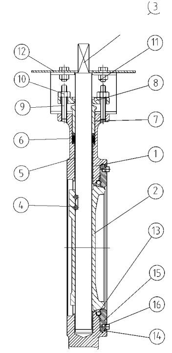
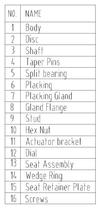
6.1 Refer Figure 1 for parts identification.
6.2 With the DISC (2) in the closed position, remove the valve from the line.
6.3 Lay the valve down with the DISC (2) in the closed position and the seat retainer side facing up.
6.4 Remove the RETAINER PLATE SCREWS (16).
6.5 Carefully clean the seat area in the BODY ⑴ and SEAT RETAINER (15).
Remove foreign material, dirt, etc. Check disc seating area for nicks or scratches.
6.6 With the DISC ⑵ is in the CLOSED position, place the new SEAT (13) on DISC (2), carefully centering it in the recess in the BODY (1).
6.7 Carefully place the SEAT RETAINER (16) in position on top of SEAT (13).
Lightly grease the threads and install the RETAINER PLATE SCREWS (16).
7.0 FIELD ADJUSTMENTS
Stem Seal Leakage 一 Should leakage occur at the stem seals, it may be stopped by retightening the GLAND NUTS (10) to the values.
NOTE: If the leakage cannot be stopped by this action, the stem seals require replacement.
8.0 FIGURES
Figure 1: DN 65-DN 300
NOTICE
Do not overtighten gland nuts, as this may cause increased operating torque and improper valve operation or closure.
горячая этикетка : high performance butterfly valves, China, manufacturers, factory, customized, wholesale, price, cheap, in stock, for sale, free sample
Отправить запрос